FA-VA 6 Antenna Analyzer
FA-VA6 Vector Antenna Analyzer
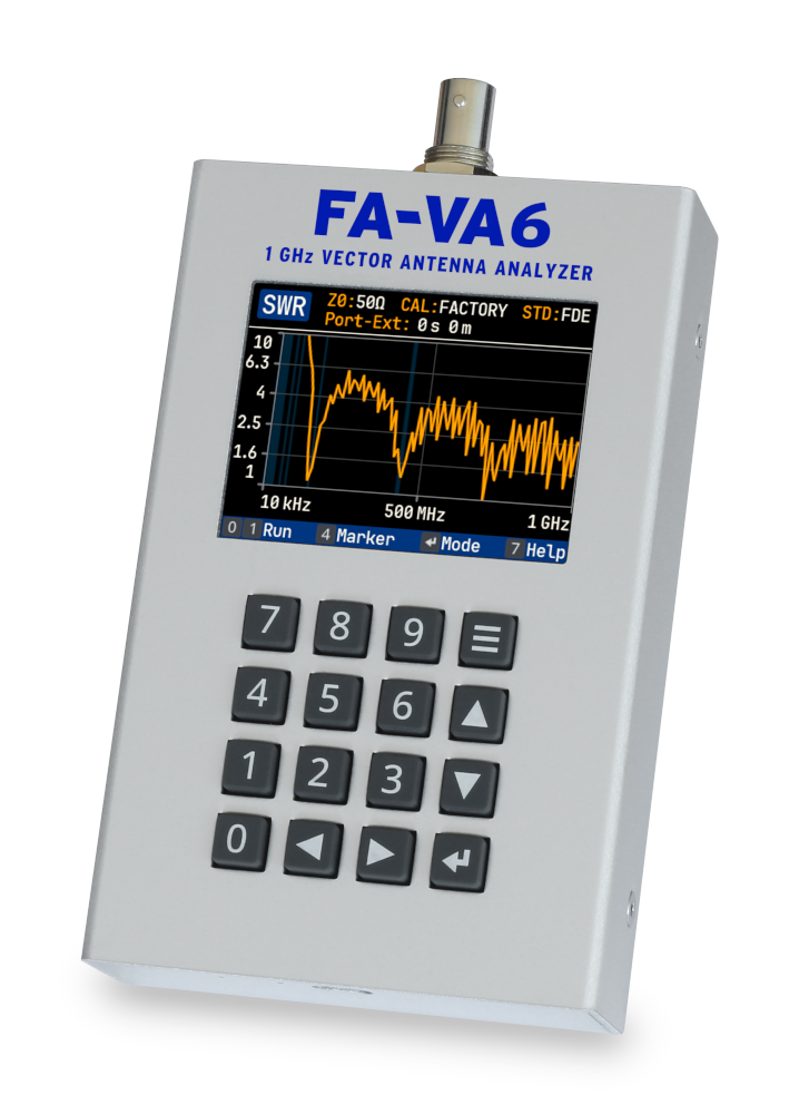
The FA-VA6 is the successor to the well-known FA-VA5 and FA-VA4 antenna analyzers and their further development. As a completely new hardware and software design, it offers significant technical improvements and numerous new features.
Powerful Hardware and Software
With a frequency range from 10 kHz to 1 GHz and an S11 dynamic range of up to 80 dB, the FA-VA6 is suitable for demanding amateur radio applications as well as professional measurement tasks.
In addition to a sunlight-readable IPS color display, an industrial-grade Li-ion cell providing more than 12 hours of operating time, a professional keypad, and a rugged aluminum enclosure, the FA-VA6 stands out primarily through its extensive measurement and analysis functions as well as its display, storage, and evaluation capabilities.
In addition to the classic single- and multi-frequency measurements, the FA-VA6 also offers time-domain measurements (TDR), cable applications for cable analysis, and technical calculators. Its intuitive, clearly structured, and responsive user interface guarantees simple and efficient operation.
The highly accurate, individual factory calibration enables immediate measurements right out of the box, while advanced users can take advantage of extensive calibration options, including the entry of calibration standard parameters.
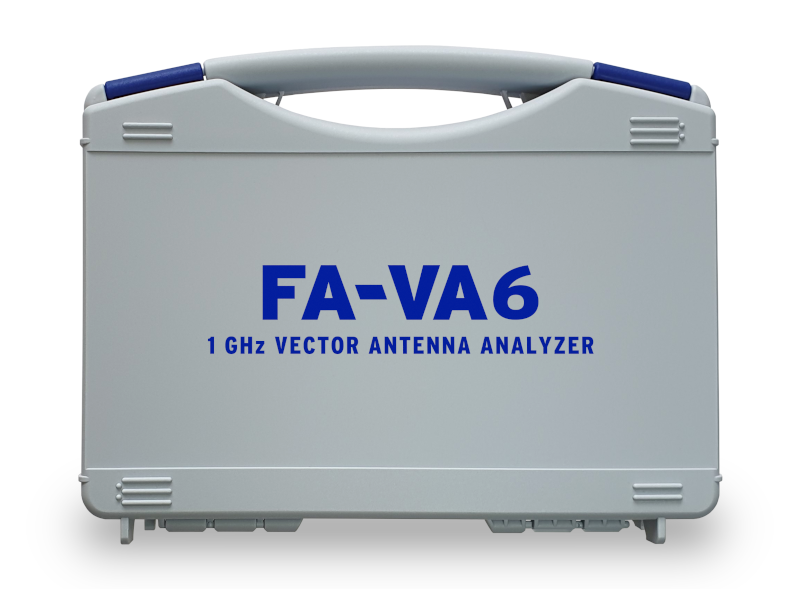
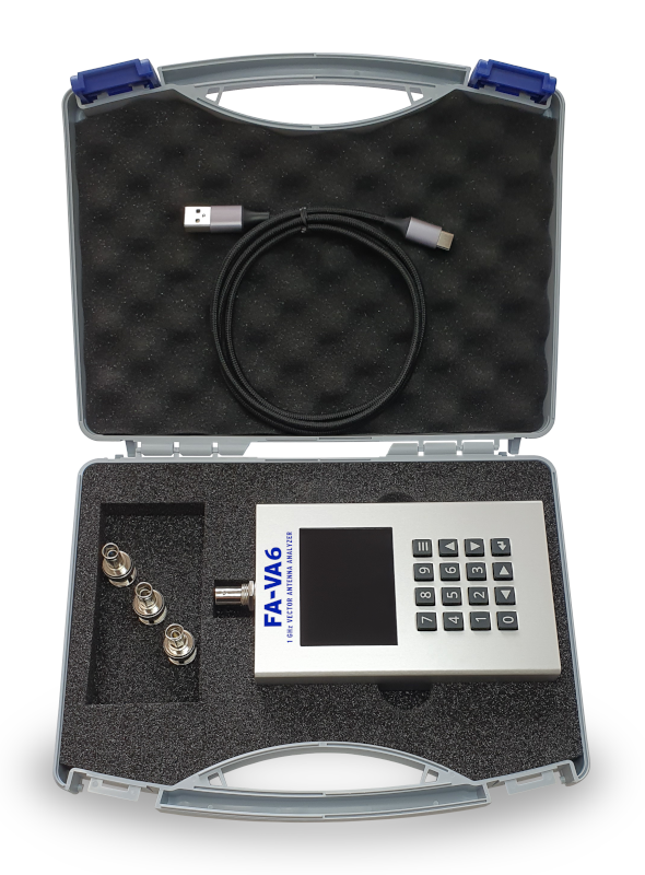
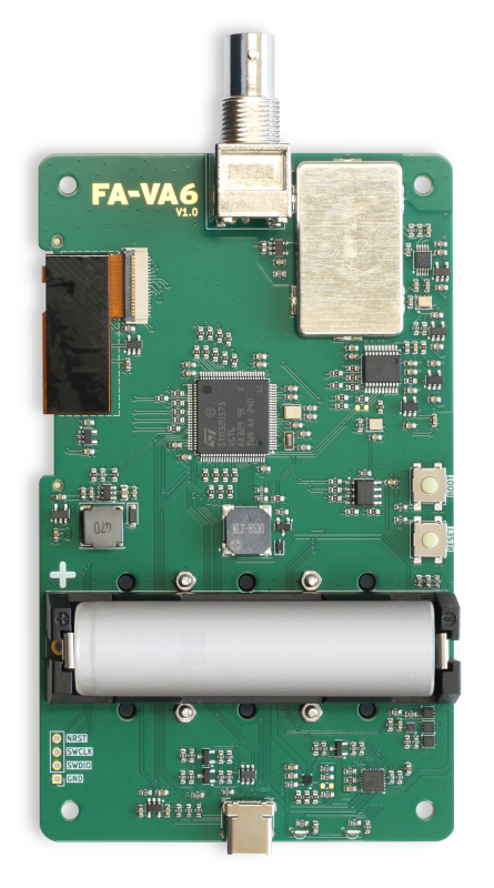
The following images of the FA-VA6, together with its accessories in the supplied carrying case, and the rear side of the circuit board provide a first impression:
PC Software and Firmware
The FA-VA6 is charged via its USB-C port, which also allows it to be connected to a PC.
The powerful VNWA PC software, available together with the FA-VA6, allows not only the import and processing of FA-VA6 measurement data, but also standalone operation of the FA-VA6 as a one-port measurement system controlled directly from a PC. An open, documented interface is also available, allowing other software applications to control the FA-VA6.
In addition, programs for
screen mirroring, for creating
screenshots, and for
firmware updates with new features and improvements are available for all major operating systems.
Currently firmware version 2.0 is available.
Publications and Field Tests
The performance and versatility of the FA-VA6 has been documented in numerous technical articles, reviews, and user reports:
- Introduction of the FA-VA6 in FUNKAMATEUR magazine, issues 05/2025 and 06/2025
- Comprehensive review in Practical Wireless magazine, issue 11/2025
- Transmission line measurements with the FA-VA6 in FUNKAMATEUR magazine, issues 02/2026 and 03/2026
- User reports and reviews on eHam.net
- Practical evaluation of the FA-VA6 by Bonito
- Presentation of the new features in firmware 2.0 in FUNKAMATEUR magazine, issue 07/2026
- Comprehensive review in RadCom magazine, issue 08/2026
Where to Get
The FA-VA6 is available for order at FUNKAMATEUR Shop, at SDR-Kits, at Bonito, at Astroradio and at Lutz-Electronics as a 99% pre-assembled kit. Included are the rugged carrying case, a self-assembly SOL calibration kit, the matching Li-ion battery, a high-quality USB cable and an individual test report.
Measurement Examples and Display Screenshots
Depending on personal preference and requirements, users can choose between the appearance profiles Modern, Classic, and Bright. The following display screenshots show example measurements and use cases.
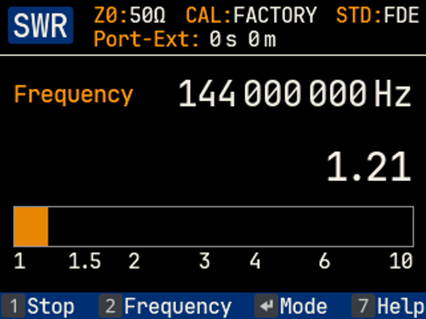
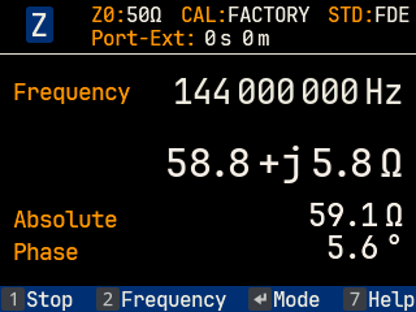
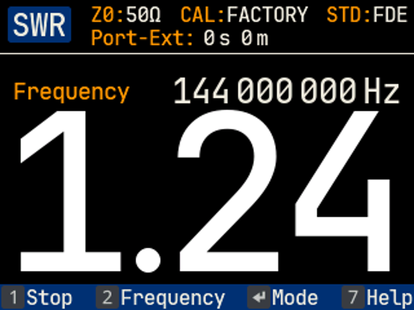
Single-frequency measurement of SWR and impedance of a dual-band mobile antenna in the 2-meter band, with an optional large SWR display for viewing from greater distances:
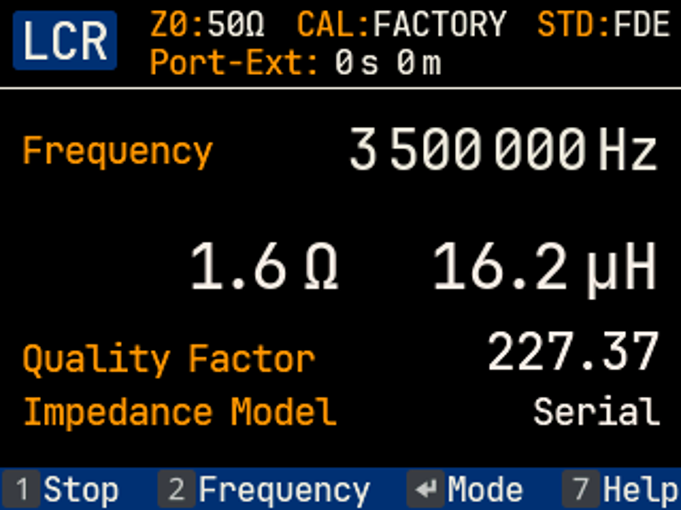
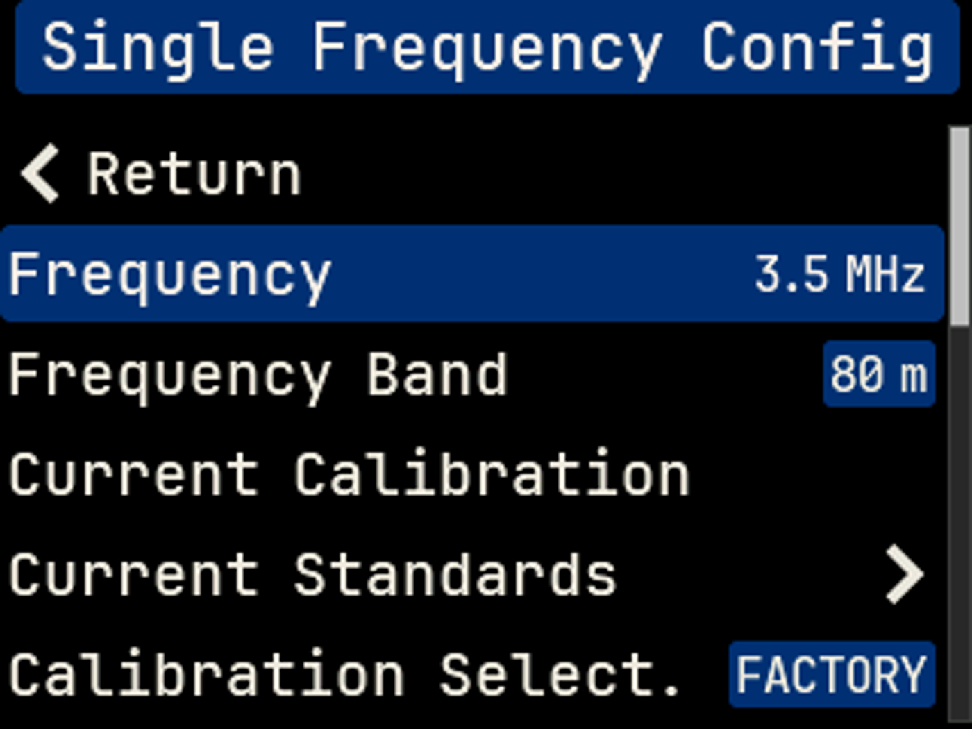
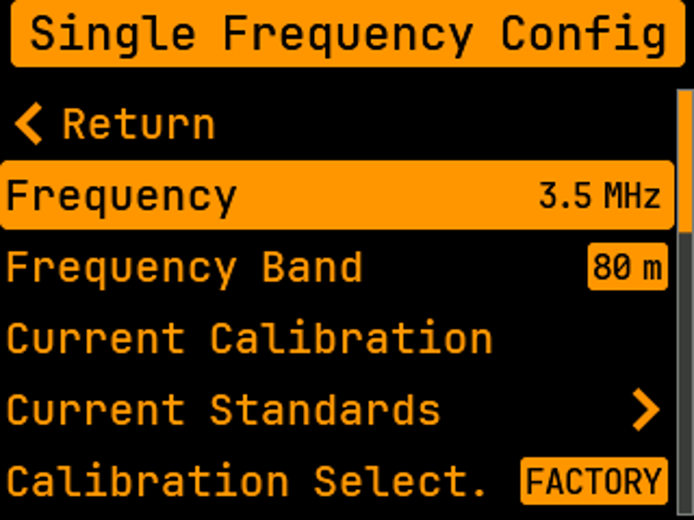
Measurement of a toroidal inductor using the LCR meter at 3.5 MHz, showing the measurement details and the single-frequency configuration (excerpt):

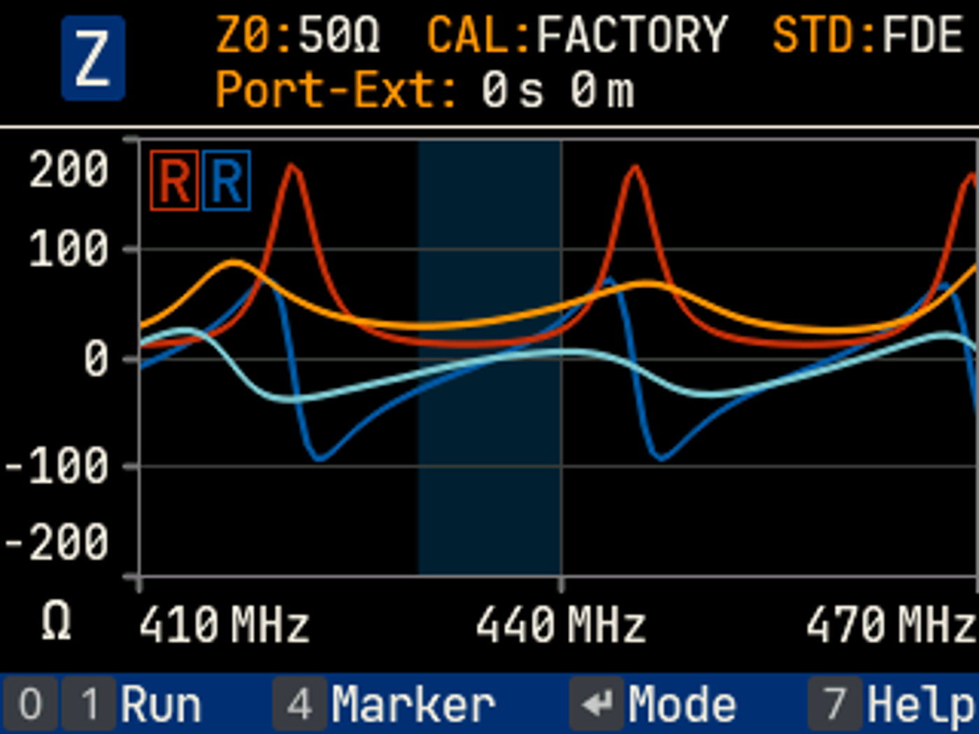
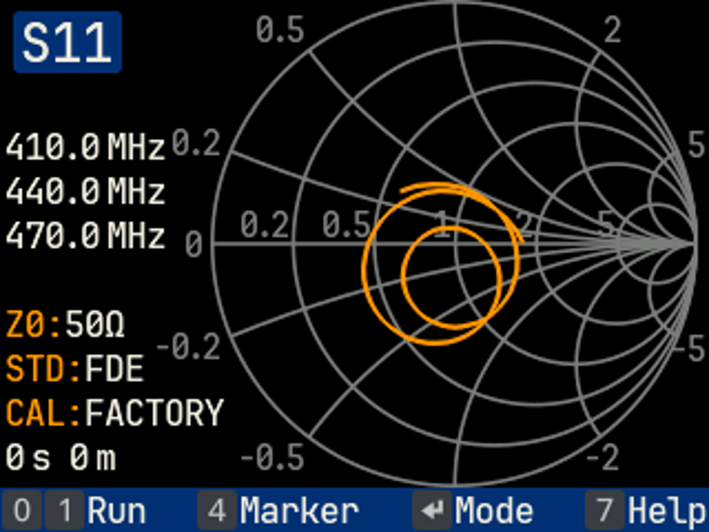
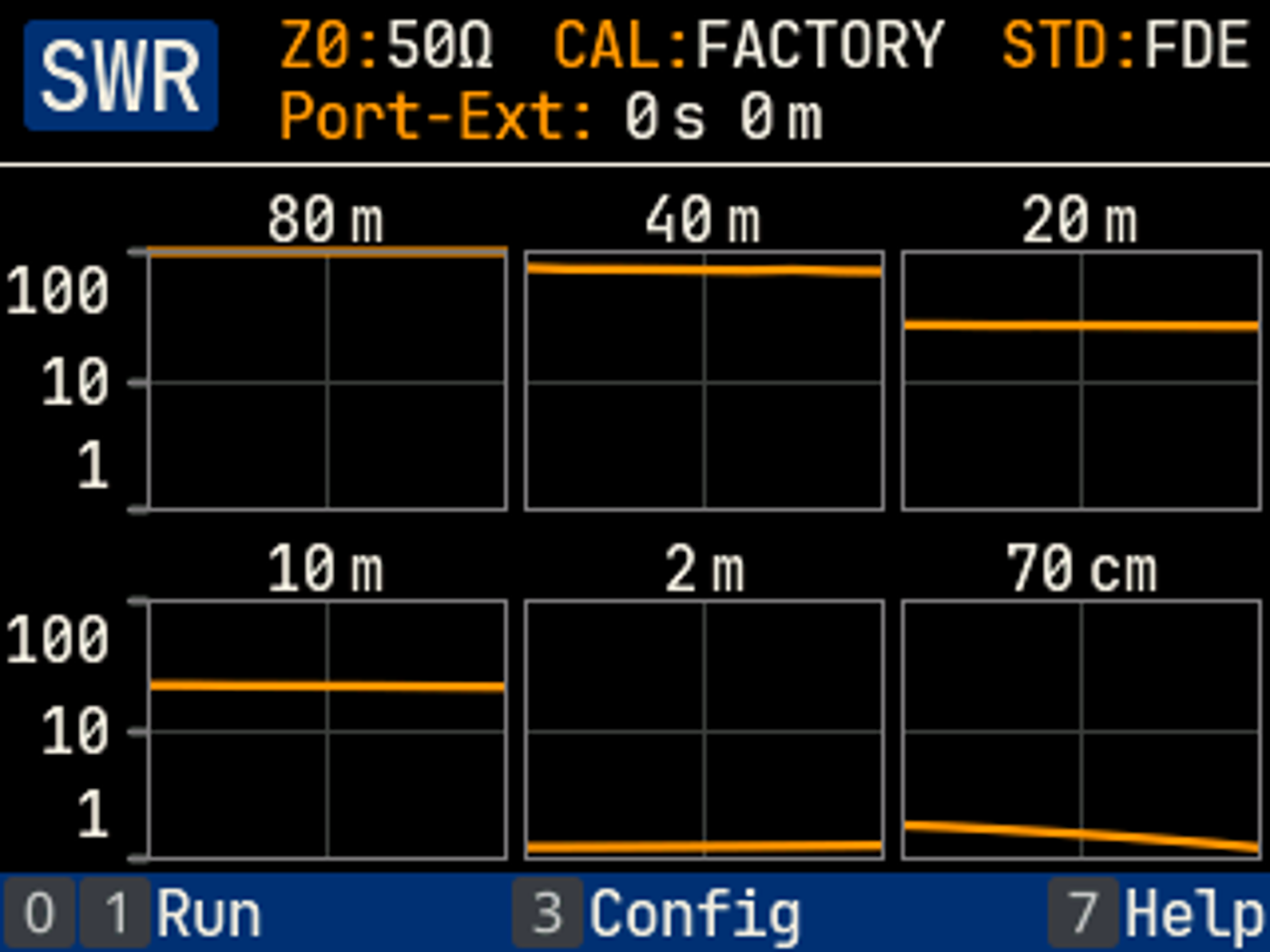
Multi-frequency measurements of SWR with activated marker, impedance view with reference trace and Smith chart in the 70 cm band on a dual-band mobile antenna:

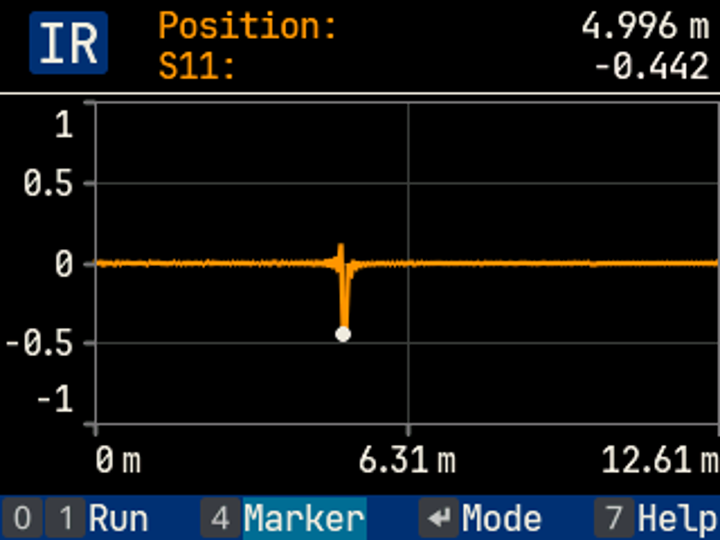
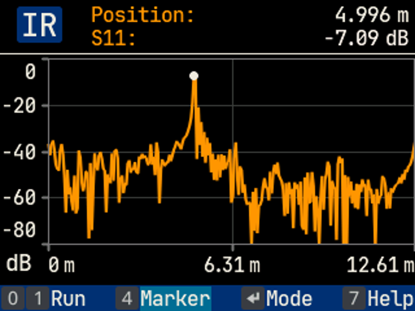
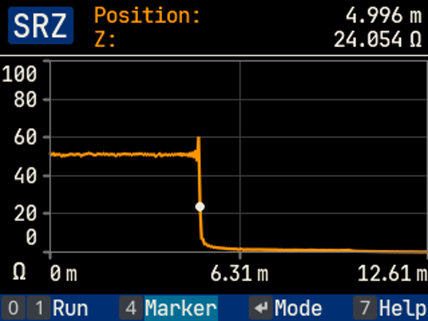
Time-domain (TDR) measurement of impulse response (reflections) and impedance of a 5-meter RG58 cable:
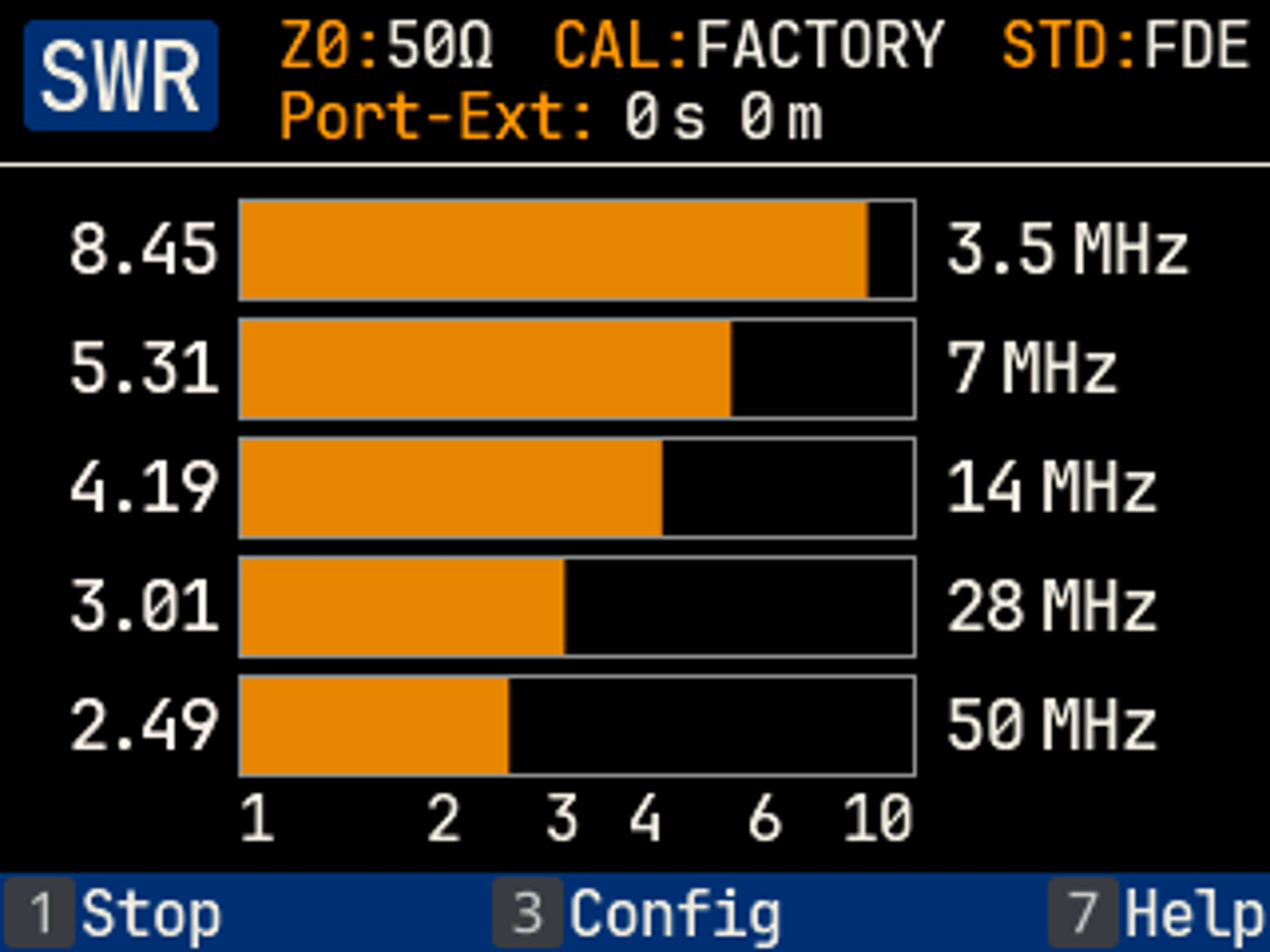
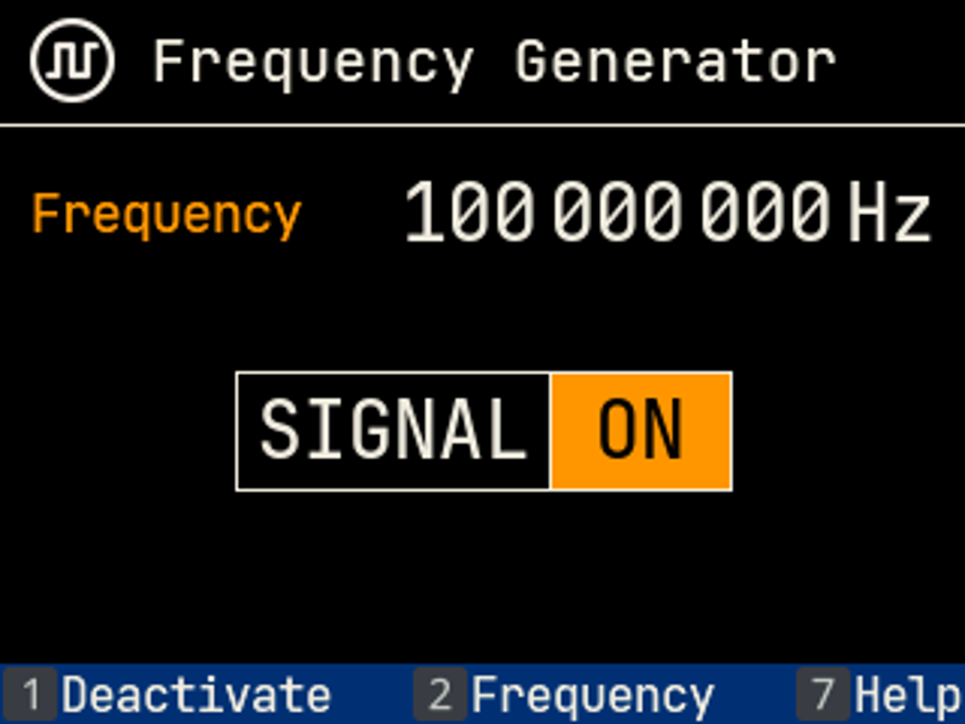
Measurement of multiband antennas with the 6-Band and 5-Frequency applications and the signal generator with activated output:
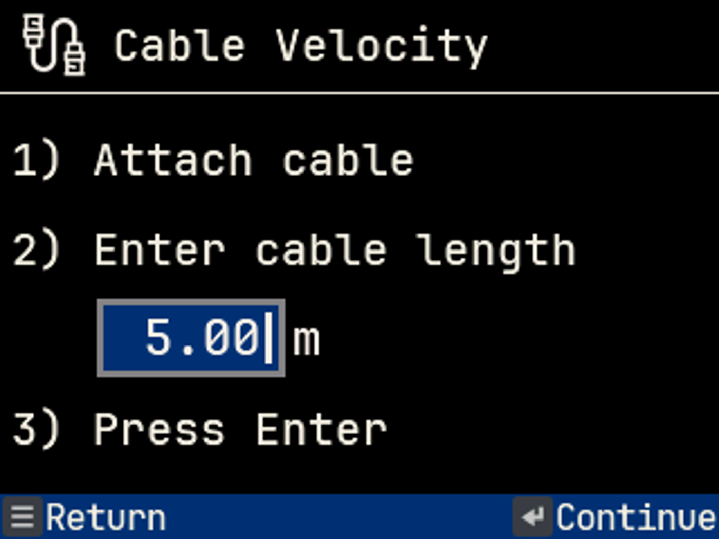
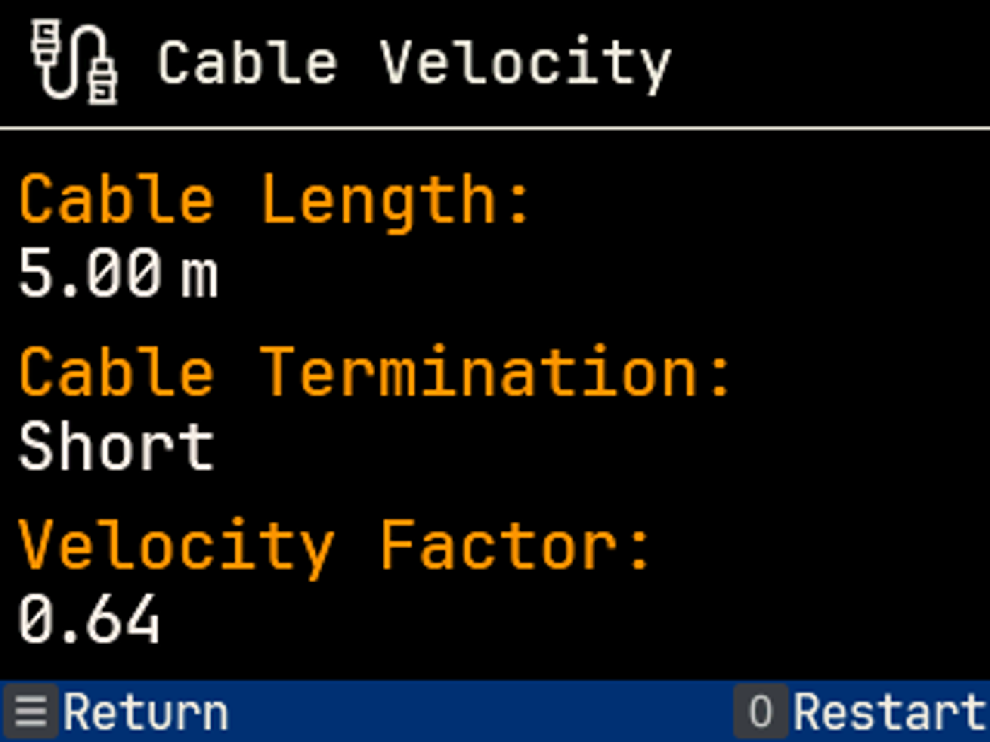
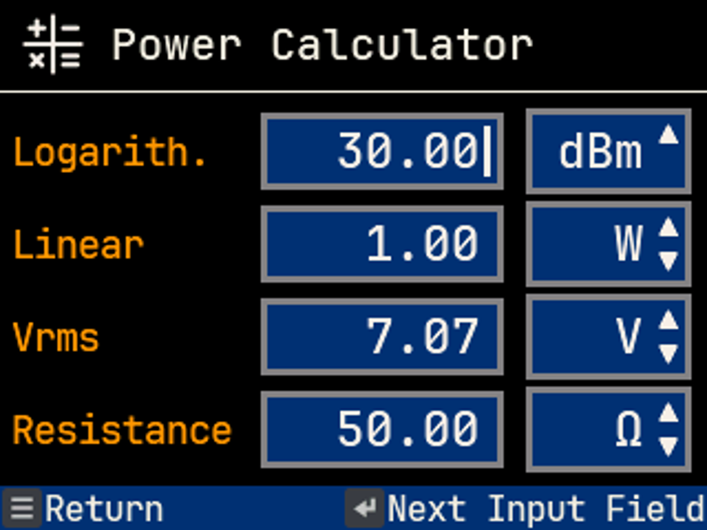
Using a cable application to determine the velocity factor and the power calculator:
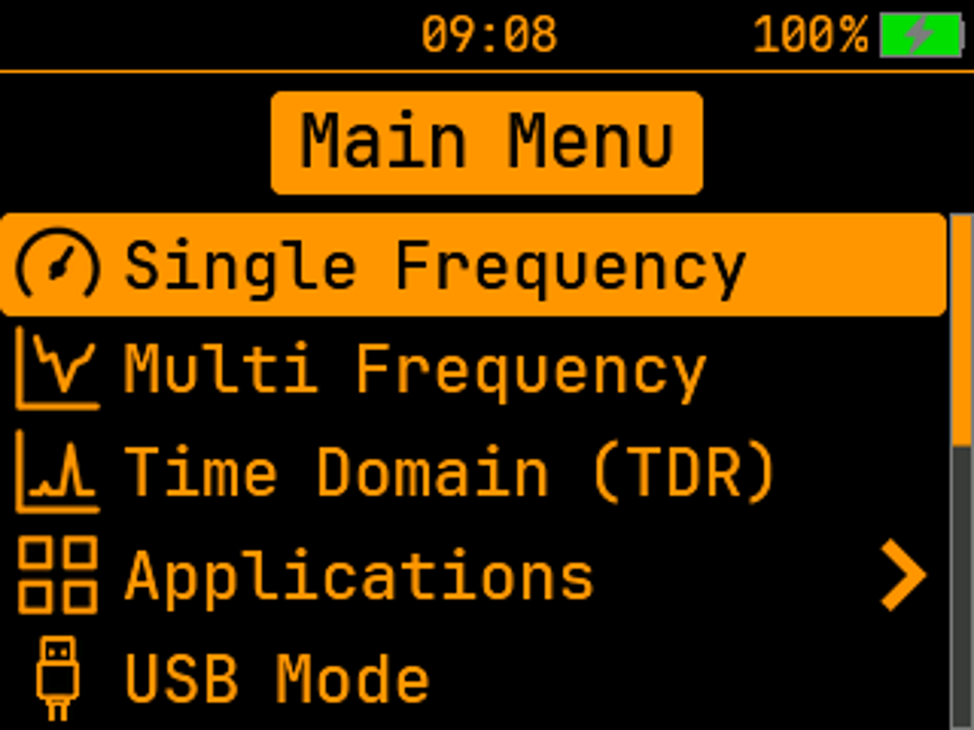
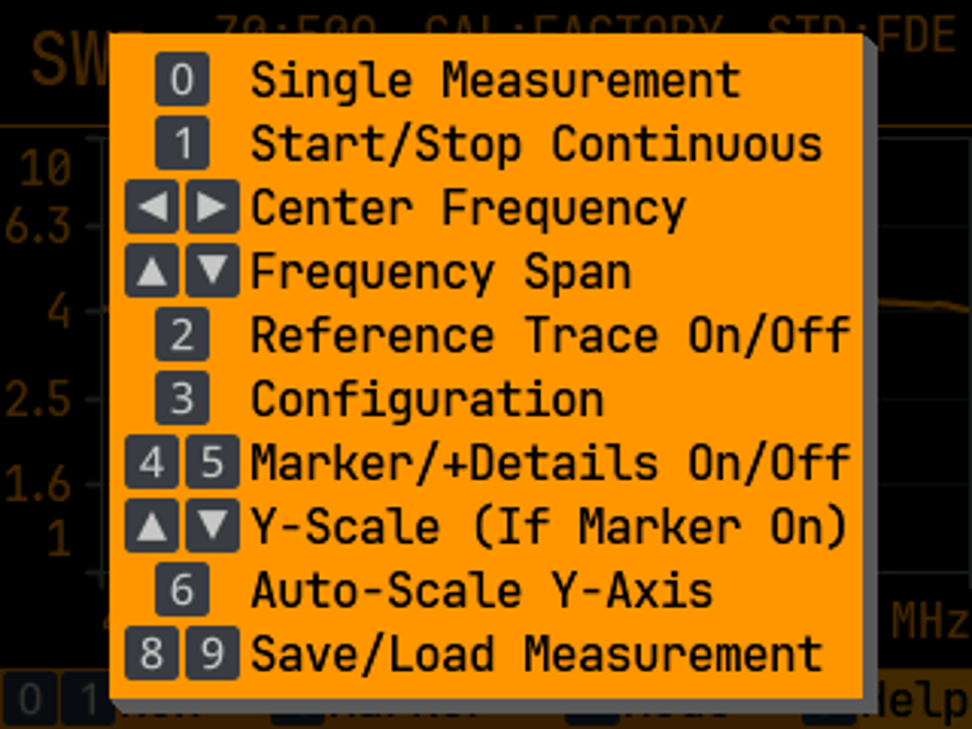
The main menu (excerpt), a settings menu (excerpt) and the help function in multi-frequency mode, shown here in the appearance profile Classic:
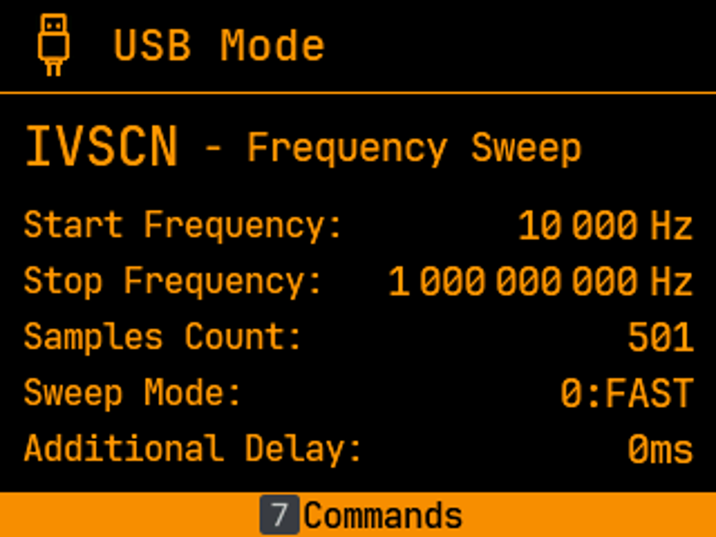
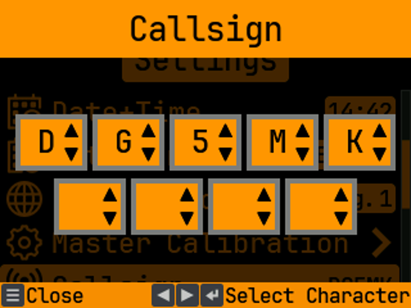
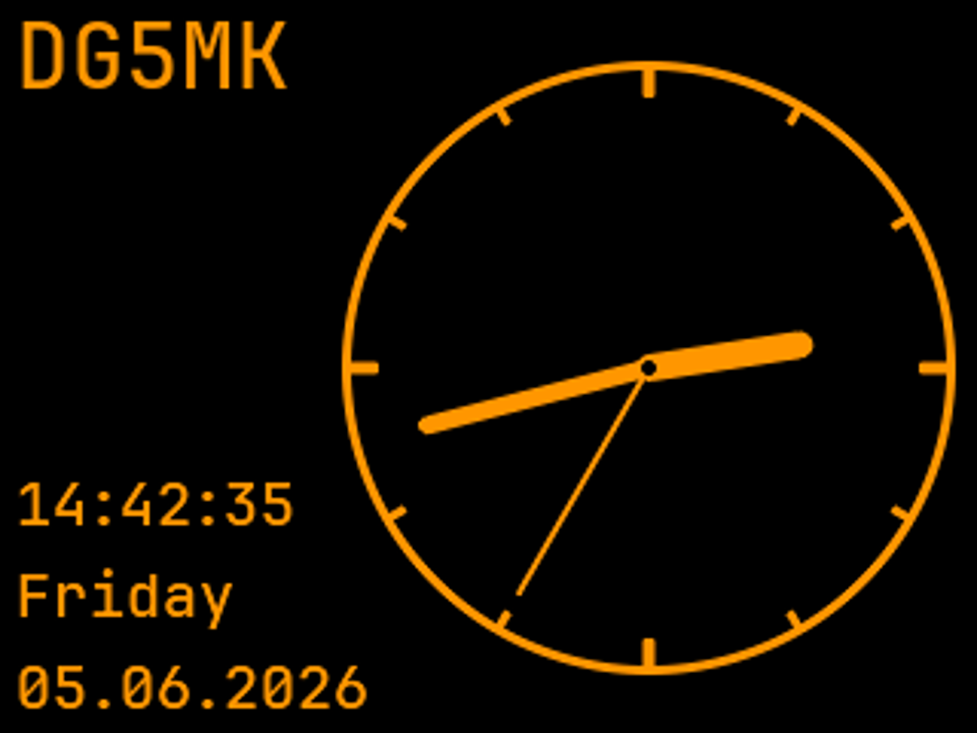
The USB operating mode, the callsign entry and the clock display, shown here in the appearance profile Classic:
Technical Data
| Component | Details |
|---|---|
| Frequency range | 10 kHz to 1 GHz (resolution 1 Hz) |
| Measurement result Single Frequency | SWR, scattering parameter S11, magnitude and phase S11, return loss, mismatch loss, impedance Z by real and imaginary part, magnitude and phase of the impedance, resistance, capacitance, inductance and quality for series and parallel equivalent circuit model of the impedance |
| Measurement result Multi Frequency | SWR, impedance Z by real and imaginary part, scattering parameter S11 as Smith chart, scattering parameter S11 in dB, all values from single frequency at the position of the marker |
| Measurement result 6-Band / 5-Frequency application |
SWR |
| Length ranges Time Domain (TDR) |
6.3 m, 12.6 m, 25.3 m, 50.6 m, 101.3 m, 202.7 m (with velocity factor 0.66) |
| Measurement result Time Domain (TDR) |
Impulse response over length, impulse response in dB over length, step response over length, step response magnitude of impedance over length |
| Time Domain (TDR) resolution | Adjacent interference points: 0.5 ns, corresponds to 0.1 m at VF = 0.66 Individual interference points: < 0.05 ns, corresponds to 0.01 m at VF = 0.66 |
| Current applications | Cable length according to known velocity factor Velocity factor according to known cable length Characteristic impedance of the cable (characteristic impedance) Cable attenuation at 10 MHz, 30 MHz, 50 MHz, 100 MHz, 200 MHz Interactive calculators for standing wave ratio (SWR), power, decibels, wavelength, and wave propagation speed |
| Display | 320x240 2.8" IPS TFT color display greater 1000 Nits brightness, Refresh rate (depending on application) 60...120 Hz |
| Dynamic range measuring chain | In each mode up to 200 MHz, 200 MHz to 600 MHz, 600 MHz to 1 GHz Precise mode: > 80 dB / 69 dB / 57 dB Balanced mode: 80 dB / 64 dB / 54 dB Fast mode: 80 dB / 60 dB / 51 dB |
| Frequency stability | 0,5 ppm |
| Signal processing | 24-bit ADC, 32-bit DSP, 64-bit calculations |
| Measurement input | BNC socket 50 Ω |
| Output signal | rectangular f = 1 MHz, R load = 50 Ω 𝑃1 = 3,2 dBm (1. harmonic, fundamental) 𝑃2 = -6,4 dBm (3. harmonic) 𝑃3 = -10,9 dBm (5. harmonic) f = 200 MHz, R load = 50 Ω 𝑃1 = 2,1 dBm (1. harmonic, fundamental) 𝑃2 = -10,0 dBm (3. harmonic) 𝑃3 = -17,6 dBm (5. harmonic) |
| Firmware | New versions free of charge, update via USB |
| Operating current and -times | 260 mA at 1000 Nits display brightness, approx. 12 h 165 mA at 500 Nits display brightness, approx. 19 h 130 mA at 300 Nits display brightness, approx. 24 h approx. 42 μA, switched off state incl. real-time clock |
| Currently supported languages | German, English, French, Italian, Spanish |
| Power supply | Lithium-Ion industrial cell 18650 |
| Battery type | Panasonic NCR18650BD 3.6 V 3180 mAh |
| Battery protection | Against reverse polarity, overcharging, deep discharge, short circuit, charging outside the operating temperature range |
| Battery charge | Via USB and built-in CI-CV charge controller with load balancing, simultaneous operation of the device possible |
| Operating and storage temperature | -20 °C bis 60 °C |
| Dimensions | 135 mm x 85 mm x 28 mm (L x B x H), without keypad and BNC socket |
| Weight | 270 g incl. battery |